
ENGINEERING AND CFD
Turbulence Inside the Tesla Turbine
Principal Investigator:
M. Eng. Stefan Klingl
Affiliation:
Bundeswehr University Munich, Neubiberg, Germany
Local Project ID:
pn29ki
HPC Platform used:
SuperMUC-NG at LRZ
Date published:
Introduction
Invented and patented by Nikola Tesla in 1913 [1], the Tesla turbine is a unique type of turbomachine that features a rotor made from stacked disks with small gaps in between, as shown in Figure 1. It is driven by a fluid that enters the disk gaps at the outer circumference and travels on a spiral path radially inward towards central exit openings. Figure 2 visualizes the path of the fluid. Rotor torque is generated purely from friction between the working fluid and the rotor disk surfaces.
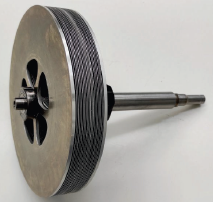
Figure 1: Sample Tesla turbine rotor with multiple disk gaps and outlet openings in the center.
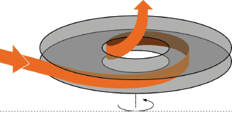
Figure 2: Simplified model of a single disk gap.
To make Tesla turbines more accessible to engineers, researchers in the past developed and validated methods for predicting turbine performance mathematically. An important aspect of this is beforehand knowledge whether the flow inside the disk gap is going to be laminar or turbulent, since modelling approaches usually target only one of those. So far, a stability boundary that separates laminar and turbulent flow regimes has been mapped out through experiments [2,3] and mathematically through linear stability analysis [4,5]. The latter searches frequencies of the flow that are amplified in time and space and possibly trigger transition to turbulence. Figure 3 shows the stability boundary from linear theory as function of Reynolds number Re* and Taylor number Ta* [5]. These can be interpreted as mass flow and rotational speed parameters respectively. Linear theory and experimental results so far do not fully agree with each other, because transition in experiments was observed earlier than predicted by theory, slightly into the laminar region of the chart. In order to verify results from linear theory and clear up the connection between stability theory and experiment, the present study describes direct numerical simulation of the turbine rotor flow.
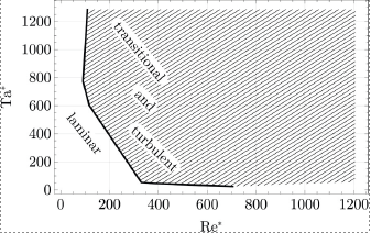
Figure 3: Stability regions from linear stability analysis.
Results and Methods
The computations are conducted without any turbulence modelling and thus accurately simulate oscillations and other unsteady features of the flow. In the turbulent case, this is computationally very expensive because the mesh has to be fine enough to resolve even the tiniest features of the flow field. In addition to the high resolution in time and space, the simulation has to run for a long period of simulation time, so that the turbulent flow field can be analyzed statistically. To cut down on computational cost, simulations are restricted to a periodic sector of the ring-shaped space between two disks. In the inlet region of the domain, the flow is artificially perturbed by a volume force that causes velocity and pressure oscillations in the flow field downstream. In the laminar region of the stability chart, it is expected that all oscillations are dampened and the flow returns to a steady, laminar state. In the transitional and turbulent regions, it is expected for certain perturbation wavelengths to be amplified further and further until the oscillations break down into a chaotic, turbulent flow field. For the turbulent operating conditions, this process can be observed in Figures 4 and 5.
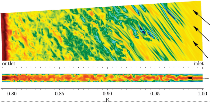
Figure 4: Velocity magnitude parallel (top) and normal (bottom) to the disk surfaces for the turbulent conditions.
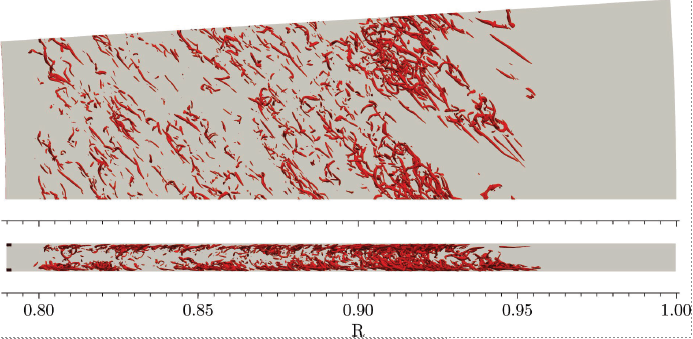
Figure 5: Visualization of turbulent structures in the velocity field from Figure 4, using the λ2-criterion.
Indeed, during the simulations with laminar operating conditions, perturbations were dampened across all wavelengths. For some wavelengths however, the dampening rate turned out to be so low, that unsteady oscillations remained in the flow field throughout the whole domain. Based on this observation, it is plausible, that the unsteady, seemingly transitional flow that was observed at these conditions in experiments is a consequence of remaining flow perturbations that originated before or during entry of the fluid into the rotor gap. For the transitional case, a small amplification rate was found for certain perturbation wavelengths in accordance with predictions from linear stability analysis. For a more detailed look into the results, please see reference [6].
Ongoing Research / Outlook
Future research could clear this up further and target other points in the stability plane. In particular, it would be interesting to investigate the role of rotation in the transition mechanism. Other than that, the simulation domain could be extended with the rotor inlet edge and possibly a nozzle to produce a more realistic flow field without the need for an artificial perturbation force.
References and Links
[1] Nikola Tesla, Turbine, Patent No. US1061206, New York, 1913.
[2] L. L. Pater et al., J. Fluids Eng., 96, no. 1, 29–34, 03 1974.
[3] G. Dibelius, D. Nendl, Reibungsturbomaschinen. Forschungsberichte des Landes Nordrhein-Westfalen, VS Verlag für Sozialwissenschaften, Wiesbaden, 1973.
[4] S. Klingl et al., Eur. J. Mech. B Fluids, 84, 455–469, 2020.
[5] S. Klingl et al., Eur. J. Mech. B Fluids, 91, 226–232, 2022.
[6] S. Klingl et al., Eur. J. Mech. B Fluids, 105, 119-137, 2024.